Browse By Unit
Peter Apps
Peter Apps
What is an Inductor? 🤔
An inductor is a coil of wire wrapped around a core that's used in electric circuits to smooth out DC current and resist sudden changes in current in the circuit. It does this by storing electrical energy in the form of magnetic fields.
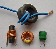
Image from wikipedia.org
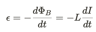
We know from Faraday's Law that the amount of magnetic flux is proportional to the induced current. We'll define a new quantity L (inductance) as a constant of proportionality such that:

Inductance is a measure of how much the inductor resists changes in its magnetic field. It can be altered by changing the number of loops in the coil, the gauge of the wire, and the material the core is made of. The SI unit for Inductance is the Henry (H).
Applying this new definition of magnetic flux to Faraday's Law, we can derive an equation for the induced EMF in terms of the current flowing through the inductor. Like before, this induced EMF opposes the change in flux.
Energy Stored in an Inductor 🔋
Let's assume you've constructed a fairly basic circuit as shown below:

When we close the switch, the current will flow through the circuit, causing an increasing flux in the inductor. The inductor will then create a counter EMF to oppose the current in the circuit. Using Kirchoff's Voltage Law we can write the following equation:
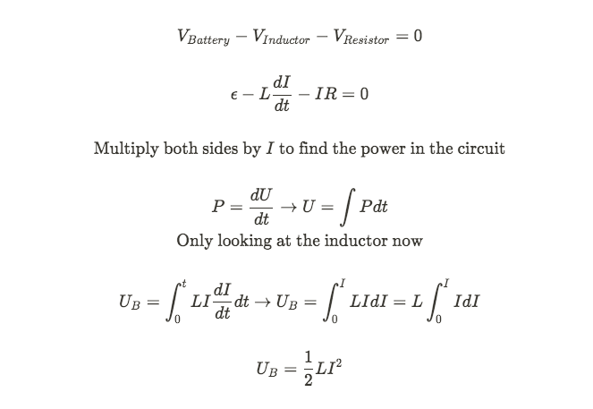
We have stored magnetic energy inside the inductor!
LR Circuit Behavior 🔍
Looking at the derivation from above, we chose to ignore the rest of the circuit to focus on the energy in the inductor. But what if we didn't...
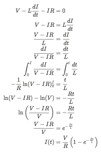
This derivation is very similar to the capacitor equations we derived in Unit 3. In this case the time constant is equal to R / L.
We can also derive an expression for the voltage drop across the induction by again using Kirchoff's Voltage Law.
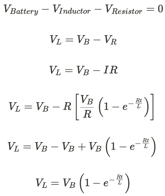
📊By graphing the equations we can determine the behavior of an inductor in the circuit.
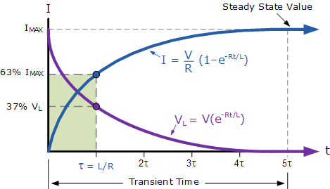
Image from electronics-tutorials.ws
When the switch is first closed, the inductor has a voltage equal to the battery. This initially prevents any current from flowing through the circuit. As t increases, the magnetic flux decreases, and more current is allowed to flow. Until we reach the steady-state value, the inductor is acting like a wire.
LC Circuit Behavior 🧲📸
The final type of circuit we need to look consists of nothing but a charged capacitor and an inductor.
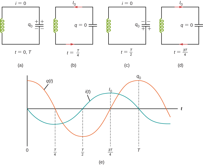
Image from phys.libretexts.org
In the beginning, all the charge is stored in the capacitor. It discharges, creating a current in the circuit (a). That current creates a changing magnetic flux in the inductor, which causes the inductor to store magnetic potential energy. Once the capacitor is discharged (b), the current drops and the inductor releases its energy to oppose the changing flux again.
This counter-current charges the capacitor (although with the opposite polarity) as shown in (c), then the cycle repeats. Image (e) shows the resulting oscillations in charge and current.
If we assume that there's no energy lost in the circuit (no resistance of any kind), then the total energy must remain constant.
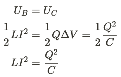
We can also use Faraday's Law to find the equations for current and charge as a function of time
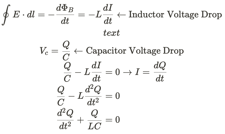
**To those who've taken AP C: Mech, this differential equation is the same form as the one you solved for simple harmonic motion. **
The solution is a function where the second derivative is the same as the function. These are trig functions!
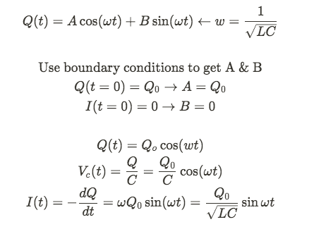
Practice Problem ✅
1)

In the circuit above, A and B are terminal to which different circuit components can be connected.
(a) Calculate the potential difference across R2 immediately after the switch S is closed in each of the following cases.
i. A 50ohm resistor connects A and B.
ii. A 40mH inductor connects A and B.
iii. An initially uncharge 0.80microfarads capacitor connects A and B.
(b) The switch gets closed at time t = 0. On the axes below, sketch the graphs of the current in the 100ohm resistor R3 versus time t for the three cases. Label the graphs R for the resistor, L for the inductor, and C for the capacitor.

Images from collegeboard.org
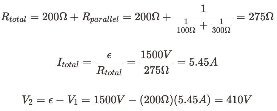
a) i) To those who've taken AP C: Mech, this differential equation is the same form as the one you solved for simple harmonic motion.
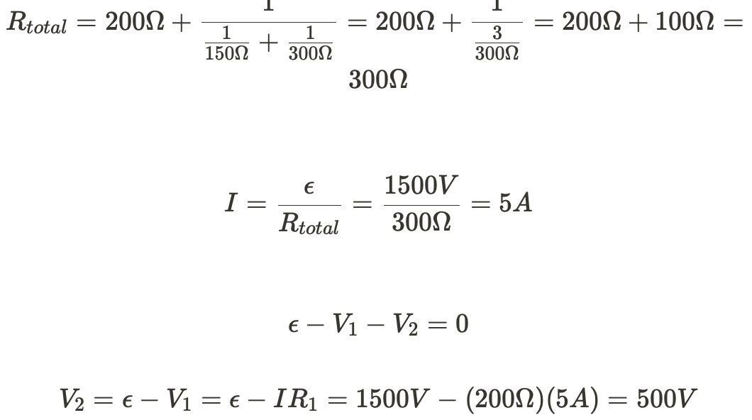
ii)An inductor acts like an open switch immediately after the switch is closed, so no current flows through the far right branch. Treat this like a series circuit.
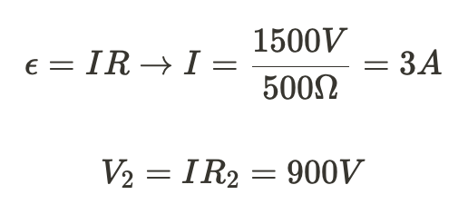
iii) The voltage drop across the capacitor is 0 immediately after the switch is closed so we can ignore it. Treat this just like we did in part (i)
b) The resistor will be a constant current since it's not time dependent. The capacitor will start with a very high current, then exponentially decrease. The inductor will begin allowing no current through then level off at some max current as
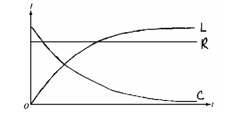
Image from collegeboard.org
<< Hide Menu
Peter Apps
Peter Apps
What is an Inductor? 🤔
An inductor is a coil of wire wrapped around a core that's used in electric circuits to smooth out DC current and resist sudden changes in current in the circuit. It does this by storing electrical energy in the form of magnetic fields.

Image from wikipedia.org
We know from Faraday's Law that the amount of magnetic flux is proportional to the induced current. We'll define a new quantity L (inductance) as a constant of proportionality such that:

Inductance is a measure of how much the inductor resists changes in its magnetic field. It can be altered by changing the number of loops in the coil, the gauge of the wire, and the material the core is made of. The SI unit for Inductance is the Henry (H).
Applying this new definition of magnetic flux to Faraday's Law, we can derive an equation for the induced EMF in terms of the current flowing through the inductor. Like before, this induced EMF opposes the change in flux.

Energy Stored in an Inductor 🔋
Let's assume you've constructed a fairly basic circuit as shown below:

When we close the switch, the current will flow through the circuit, causing an increasing flux in the inductor. The inductor will then create a counter EMF to oppose the current in the circuit. Using Kirchoff's Voltage Law we can write the following equation:

We have stored magnetic energy inside the inductor!
LR Circuit Behavior 🔍
Looking at the derivation from above, we chose to ignore the rest of the circuit to focus on the energy in the inductor. But what if we didn't...

This derivation is very similar to the capacitor equations we derived in Unit 3. In this case the time constant is equal to R / L.
We can also derive an expression for the voltage drop across the induction by again using Kirchoff's Voltage Law.

📊By graphing the equations we can determine the behavior of an inductor in the circuit.

Image from electronics-tutorials.ws
When the switch is first closed, the inductor has a voltage equal to the battery. This initially prevents any current from flowing through the circuit. As t increases, the magnetic flux decreases, and more current is allowed to flow. Until we reach the steady-state value, the inductor is acting like a wire.
LC Circuit Behavior 🧲📸
The final type of circuit we need to look consists of nothing but a charged capacitor and an inductor.

Image from phys.libretexts.org
In the beginning, all the charge is stored in the capacitor. It discharges, creating a current in the circuit (a). That current creates a changing magnetic flux in the inductor, which causes the inductor to store magnetic potential energy. Once the capacitor is discharged (b), the current drops and the inductor releases its energy to oppose the changing flux again.
This counter-current charges the capacitor (although with the opposite polarity) as shown in (c), then the cycle repeats. Image (e) shows the resulting oscillations in charge and current.
If we assume that there's no energy lost in the circuit (no resistance of any kind), then the total energy must remain constant.

We can also use Faraday's Law to find the equations for current and charge as a function of time

**To those who've taken AP C: Mech, this differential equation is the same form as the one you solved for simple harmonic motion. **
The solution is a function where the second derivative is the same as the function. These are trig functions!

Practice Problem ✅
1)

In the circuit above, A and B are terminal to which different circuit components can be connected.
(a) Calculate the potential difference across R2 immediately after the switch S is closed in each of the following cases.
i. A 50ohm resistor connects A and B.
ii. A 40mH inductor connects A and B.
iii. An initially uncharge 0.80microfarads capacitor connects A and B.
(b) The switch gets closed at time t = 0. On the axes below, sketch the graphs of the current in the 100ohm resistor R3 versus time t for the three cases. Label the graphs R for the resistor, L for the inductor, and C for the capacitor.

Images from collegeboard.org
a) i) To those who've taken AP C: Mech, this differential equation is the same form as the one you solved for simple harmonic motion.

ii)An inductor acts like an open switch immediately after the switch is closed, so no current flows through the far right branch. Treat this like a series circuit.

iii) The voltage drop across the capacitor is 0 immediately after the switch is closed so we can ignore it. Treat this just like we did in part (i)

b) The resistor will be a constant current since it's not time dependent. The capacitor will start with a very high current, then exponentially decrease. The inductor will begin allowing no current through then level off at some max current as

Image from collegeboard.org

© 2024 Fiveable Inc. All rights reserved.