Browse By Unit
Peter Apps
Peter Apps
5.0: Overview 🧭
You've made it! 🏁It's the final unit in AP® C: E&M. Here, we're going to take a look at how electric circuits can be used to create magnets. We'll look at several applications including motors, rail guns, and transformers. We'll also do a brief look at Maxwell's Equations, four equations that set the basis for all of the E&M concepts we've covered in the course. This content will make up 14-20% of the AP exam. When you're ready, the Personal Progress Check has around 25 MCQ and 1 FRQ for you to practice on.
5.1: Electromagnetic Induction
Making Magnets from Electricity 🧙
Electromagnetic Induction is the process of using magnetic fields to produce a voltage. If that voltage is produces in a complete circuit, it can create a current. We've seen in Unit 4 that current moving through a wire creates a magnetic field, all we're doing here is reversing that process.
Take a few minutes to play around with this PhET simulation, especially the Pickup Coil Tab. What does it take to make the bulb light up?
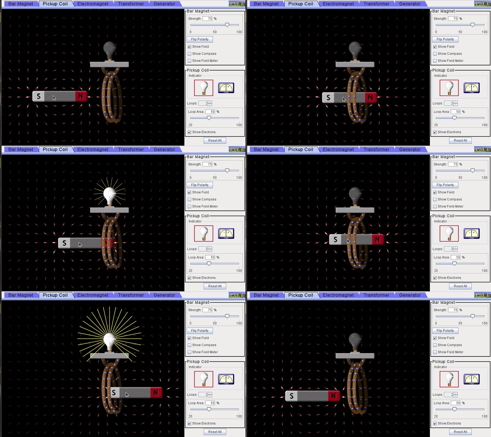
Image created by the author using PhET
The magnet needs to be moving! Just like we needed a moving charge to create a magnetic field, we need a moving magnetic field to induce a potential difference.
Magnetic Flux 🌐
Remember back in Unit 2, we looked at the concept of electric flux to use Gauss' Law. Now we're going to look at magnetic flux to use Faraday's Law. The flux can be found using the equation below: (This looks very similar to electric flux)

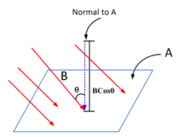
Image from electricalacademia.com
B is the magnetic field strength, dA is a tiny chunk of the area we're measuring the flux through, and θ is the angle between the magnetic field vector and the area vector. Looking at the units for the flux, we can see that it would be Tm^2, which is equivalent to a Weber (Wb).
The magnetic flux can be changed in 3 ways:

Image from physics.stackexchange.com/
Faraday's Law & Lenz's Law 🔦
Faraday's Law deals with how a change in the magnetic flux induces a current in a conductor and therefore a source of Electromotive Force (EMF).

This is the simplest case, useful for a single loop of wire. However the induced EMF can be amplified by using more turns of wire, creating a transformer**.**

N represents the number of loops of wire.
Lenz's Law deals with the negative sign in Faraday's Law. It gives us the direction of the induced EMF and lets us find the direction of the induced current, as well (you do remember the Right-Hand Rule, right?). In the simplest sense, Lenz's Law says that the induced EMF in a loop or wire will always oppose the change in magnetic flux that caused it.
The basic reasoning for this comes from the Law of Conservation of Energy. If the induced EMF was in the same direction as the flux, we would enter a positive feedback loop that would produce infinite EMF (and infinite energy).
** For some simple DIY examples of Lenz's Law in action, check out this video by D!NG, or this one by Veritasium.**
Ok, now let's take a look at a bunch of examples:
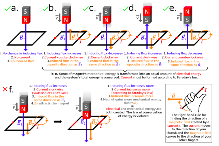
Image from wikipedia
- In case (a) the magnet is stationary. There is no changing flux, so there is no current or opposing induced magnetic field.
- Case (b) shows the magnet falling. The flux is increasing because the magnetic field B1 is getting stronger, so there must be an induced magnetic force that opposes it (B2) pointing upwards. Using the RHR, we can see that the induced current in the loop must be traveling CCW to produce this opposing field.
- Case (c) shows the reverse of case (b). The flux is decreasing because the magnet is moving away, so the induced magnetic field must be pointing the same direction as B1 to counteract the weakening field. This induced field is created by the current traveling in a CW direction.
Practical Applications ⚡
Transformers are frequently used to step up or step down the voltage of a circuit. For example, your cell phone needs 5V to charge, but we plug it into a wall socket delivering 120V (or 240V if you're outside of North America). 🔌
A transformer will step up or step down the voltage, depending on the number of loops of wire. If there are more loops on the primary (in) side than on the secondary (out) side, the voltage steps down. If the secondary side has more turns, the voltage steps up.
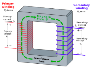
Image from wikipedia
We also see similar applications of Faraday's Law in microphones and headphones. If you'd like a more detailed look at how those are constructed, check out this infografic.
🔦 Motional EMF devices are another useful application. Objects such as the shake flashlight slide an object back and forth in a magnetic field to generate an EMF without the use of batteries.

Image via amazon.com
Let's look at the inner workings here:
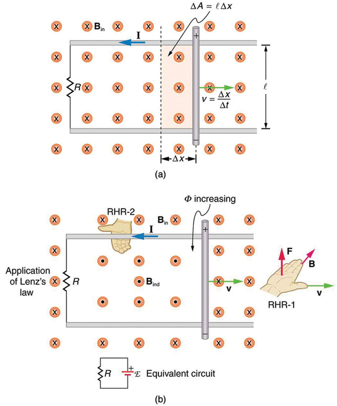
Image from lumenlearning.com
In image (a), we have a metal bar that is being pushed to the right at a constant velocity, v. As the bar moves along the rails, it sweeps over an area A = l \ Δ x. Because the area is increasing, this increases the magnetic flux as well ( ΦB = ∫ B * dA = BA cos θ = BA ). The increasing flux into the page must be opposed by an induced field pointing into the page.
Using RHR #2, and curling our fingers in the direction of the B field (into the page outside the loop and out of the page inside the loop), we see that the current flows in a CCW direction as shown in image (b).
Now let's find the EMF induced in the circuit. (Drop the - sign since we know the direction of the current, and N = 1 since there's only one loop)

We can also derive an equation for the magnitude of the current in the wire

Maxwell's Equations 👨🔬
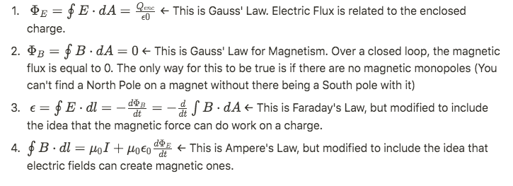
Maxwell's 4 equations describe the fundamental nature of electrical and magnetic fields and their interactions. We've actually studied all of them throughout this course (even if you didn't know it yet😉). So here they are in all their glory.
Practice Problems ✅
Images from collegeboard.org
Answers:
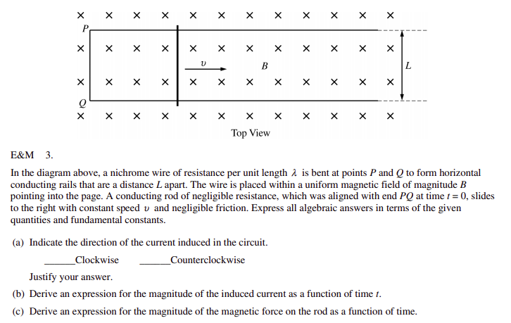
a) 2 ways to answer this one, both reveal that CCW is the direction
- i) There is an increasing magnetic flux since the rod is covering a larger area. The induced EMF must be in opposition to that flux, so the induced field must point out of the paper. Using the RHR, the current can be found to be moving in the CCW direction
- ii) The positive charge carriers in the rod experience a force pushing them towards the top of the page (using the RHR and F = qv * B where v is to the right, and B is into the page). Because the charge carriers are pushed towards the top of the page, they will travel in a CCW direction around the loop
b) Use Ohm's Law, and Faraday's Law
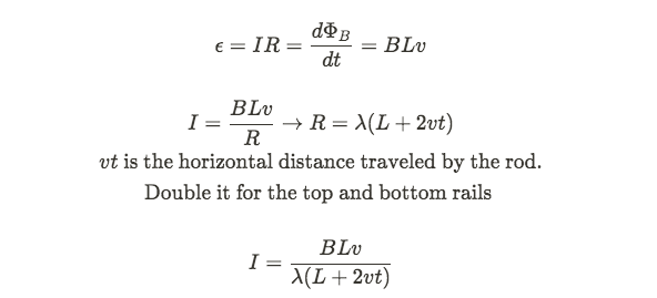
c)

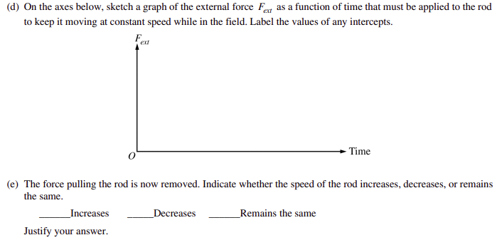
d) To keep the rod moving at a constant speed, Fext = Fb. At t = 0, FB = B^2 L v / λ (answer from part c) and as t increases, the graph should decrease.

Image from collegeboard.org
e) The speed of the rod will decrease. The only force that now acts on the rod is the magnetic force which is acting in the opposite direction as the rod's velocity. This means the acceleration on the rod is negative which causes its speed to decrease.
<< Hide Menu
Peter Apps
Peter Apps
5.0: Overview 🧭
You've made it! 🏁It's the final unit in AP® C: E&M. Here, we're going to take a look at how electric circuits can be used to create magnets. We'll look at several applications including motors, rail guns, and transformers. We'll also do a brief look at Maxwell's Equations, four equations that set the basis for all of the E&M concepts we've covered in the course. This content will make up 14-20% of the AP exam. When you're ready, the Personal Progress Check has around 25 MCQ and 1 FRQ for you to practice on.
5.1: Electromagnetic Induction
Making Magnets from Electricity 🧙
Electromagnetic Induction is the process of using magnetic fields to produce a voltage. If that voltage is produces in a complete circuit, it can create a current. We've seen in Unit 4 that current moving through a wire creates a magnetic field, all we're doing here is reversing that process.
Take a few minutes to play around with this PhET simulation, especially the Pickup Coil Tab. What does it take to make the bulb light up?

Image created by the author using PhET
The magnet needs to be moving! Just like we needed a moving charge to create a magnetic field, we need a moving magnetic field to induce a potential difference.
Magnetic Flux 🌐
Remember back in Unit 2, we looked at the concept of electric flux to use Gauss' Law. Now we're going to look at magnetic flux to use Faraday's Law. The flux can be found using the equation below: (This looks very similar to electric flux)


Image from electricalacademia.com
B is the magnetic field strength, dA is a tiny chunk of the area we're measuring the flux through, and θ is the angle between the magnetic field vector and the area vector. Looking at the units for the flux, we can see that it would be Tm^2, which is equivalent to a Weber (Wb).
The magnetic flux can be changed in 3 ways:

Image from physics.stackexchange.com/
Faraday's Law & Lenz's Law 🔦
Faraday's Law deals with how a change in the magnetic flux induces a current in a conductor and therefore a source of Electromotive Force (EMF).

This is the simplest case, useful for a single loop of wire. However the induced EMF can be amplified by using more turns of wire, creating a transformer**.**

N represents the number of loops of wire.
Lenz's Law deals with the negative sign in Faraday's Law. It gives us the direction of the induced EMF and lets us find the direction of the induced current, as well (you do remember the Right-Hand Rule, right?). In the simplest sense, Lenz's Law says that the induced EMF in a loop or wire will always oppose the change in magnetic flux that caused it.
The basic reasoning for this comes from the Law of Conservation of Energy. If the induced EMF was in the same direction as the flux, we would enter a positive feedback loop that would produce infinite EMF (and infinite energy).
** For some simple DIY examples of Lenz's Law in action, check out this video by D!NG, or this one by Veritasium.**
Ok, now let's take a look at a bunch of examples:

Image from wikipedia
- In case (a) the magnet is stationary. There is no changing flux, so there is no current or opposing induced magnetic field.
- Case (b) shows the magnet falling. The flux is increasing because the magnetic field B1 is getting stronger, so there must be an induced magnetic force that opposes it (B2) pointing upwards. Using the RHR, we can see that the induced current in the loop must be traveling CCW to produce this opposing field.
- Case (c) shows the reverse of case (b). The flux is decreasing because the magnet is moving away, so the induced magnetic field must be pointing the same direction as B1 to counteract the weakening field. This induced field is created by the current traveling in a CW direction.
Practical Applications ⚡
Transformers are frequently used to step up or step down the voltage of a circuit. For example, your cell phone needs 5V to charge, but we plug it into a wall socket delivering 120V (or 240V if you're outside of North America). 🔌
A transformer will step up or step down the voltage, depending on the number of loops of wire. If there are more loops on the primary (in) side than on the secondary (out) side, the voltage steps down. If the secondary side has more turns, the voltage steps up.

Image from wikipedia
We also see similar applications of Faraday's Law in microphones and headphones. If you'd like a more detailed look at how those are constructed, check out this infografic.
🔦 Motional EMF devices are another useful application. Objects such as the shake flashlight slide an object back and forth in a magnetic field to generate an EMF without the use of batteries.

Image via amazon.com
Let's look at the inner workings here:

Image from lumenlearning.com
In image (a), we have a metal bar that is being pushed to the right at a constant velocity, v. As the bar moves along the rails, it sweeps over an area A = l \ Δ x. Because the area is increasing, this increases the magnetic flux as well ( ΦB = ∫ B * dA = BA cos θ = BA ). The increasing flux into the page must be opposed by an induced field pointing into the page.
Using RHR #2, and curling our fingers in the direction of the B field (into the page outside the loop and out of the page inside the loop), we see that the current flows in a CCW direction as shown in image (b).
Now let's find the EMF induced in the circuit. (Drop the - sign since we know the direction of the current, and N = 1 since there's only one loop)

We can also derive an equation for the magnitude of the current in the wire

Maxwell's Equations 👨🔬
Maxwell's 4 equations describe the fundamental nature of electrical and magnetic fields and their interactions. We've actually studied all of them throughout this course (even if you didn't know it yet😉). So here they are in all their glory.

Practice Problems ✅


Images from collegeboard.org
Answers:
a) 2 ways to answer this one, both reveal that CCW is the direction
- i) There is an increasing magnetic flux since the rod is covering a larger area. The induced EMF must be in opposition to that flux, so the induced field must point out of the paper. Using the RHR, the current can be found to be moving in the CCW direction
- ii) The positive charge carriers in the rod experience a force pushing them towards the top of the page (using the RHR and F = qv * B where v is to the right, and B is into the page). Because the charge carriers are pushed towards the top of the page, they will travel in a CCW direction around the loop
b) Use Ohm's Law, and Faraday's Law

c)

d) To keep the rod moving at a constant speed, Fext = Fb. At t = 0, FB = B^2 L v / λ (answer from part c) and as t increases, the graph should decrease.

Image from collegeboard.org
e) The speed of the rod will decrease. The only force that now acts on the rod is the magnetic force which is acting in the opposite direction as the rod's velocity. This means the acceleration on the rod is negative which causes its speed to decrease.

© 2024 Fiveable Inc. All rights reserved.